Mineral dust aerosols: Difference between revisions
| Line 184: | Line 184: | ||
'''''Sajeev Philip wrote:''''' | '''''Sajeev Philip wrote:''''' | ||
<blockquote>We have added a new PM2.5 dust emission inventory (in addition to the default mineral dust simulation) into GEOS-Chem, termed as | <blockquote>We have added a new PM2.5 dust emission inventory (in addition to the default mineral dust simulation) into GEOS-Chem, termed as '''A'''nthropogenic '''F'''ugitive, '''C'''ombustion and '''I'''ndustrial '''D'''ust (AFCID). In this dataset of fine anthropogenic dust, combustion and industrial sources dominate in most regions. The more commonly used term of fugitive dust is primarily coarse and not well represented in this fine dust inventory. Inclusion of AFCID improved the comparison of simulated dust and total PM2.5 mass in comparison with in situ observations (Philip et al., ERL, 2017). Users have the option to turn on/off this new inventory within the module: <tt>GeosCore/HEMCO/Extensions/hcox_dustdead_mod.F</tt></blockquote> | ||
'''Reference:''' | '''Reference:''' | ||
Revision as of 18:04, 6 June 2018
On this page we provide information about the treatment of mineral dust aerosols in GEOS-Chem.
Overview
From Fairlie et al [2007]:
We implemented two dust mobilization schemes in GEOS-Chem: (1) the scheme of Ginoux et al. (2004, hereafter G04), developed for the GOCART CTM and (2) the dust entrainment and deposition (DEAD) scheme of Zender et al. (2003a, b hereafter Z03a,b). Both schemes treat the vertical dust flux as proportional to the horizontal saltation flux. The DEAD scheme (Z03) follows MB95 in computing a total horizontal saltation flux, Qs, based on the theory of White (1979):
               RHOair                 (      U*,t  )   (      U*,t   )^2
     Qs = Cz * --------- * Ustar^3 *  ( 1 - ------ ) * ( 1 + ------- )      (1)
                  g                   (       U*   )   (       U*    )
where U* is the friction velocity, U*,t(D) is the threshold friction velocity, RHOair is the air density, g is the acceleration of gravity, and Cz is a global tuning parameter. Qs is computed at D = 75μm, where U*,t is a minimum, and the total vertical flux is given by:
F = Am * Sz * ALPHA * Qs (2)
where the sandblasting mass efficiency, ALPHA, depends on the fraction Mclay of clay in the soil, Am is the fractional area of land suitable for mobilization, and Sz is the ‘‘erodibility,’’ an efficiency factor that favors emissions from specified geographic features. We followed Z03b in using ‘‘geomorphic erodibility,’’ which depends on upstream runoff area, and set Mclay = 0.2 globally. We computed U from the 10-m wind speed assuming neutral stability below and used a roughness length Z0 = 100 mm, recommended by Z03a for dust mobilization candidate cells. F is distributed by particle size as a globally uniform tri-modal lognormal probability density function, which we project on to the selected size bins specified above.
The GOCART scheme (G04) follows Gillette and Passi (1988) in computing a size segregated vertical dust flux, Fp, for each size class, p:
Fp = Cg * S * sp * U10^2 * ( U10 - U*,t ) (3)
where the ‘‘source function,’’ S, serves the same role as the product Am * Sz in DEAD (Eq. (2)), sp is the mass fraction applied to each size class, U10 is the 10-m wind speed, and Cg is a global constant. S confines dust emissions to topographic depressions in desert and semi-desert areas of the world (Ginoux et al., 2001, hereafter G01) and is time invariant....
Although the DEAD and GOCART schemes differ in detail, they differ most fundamentally in representing the role of vegetation. GOCART restricts emissions to persistent arid regions, whereas DEAD permits regions that become seasonally devegetated to mobilize....
--Bob Y. (talk) 16:32, 26 October 2015 (UTC)
Recent updates
The following updates were made to Fairlie et al [2007]:
Sub-micron dust mass partitioning change
This update was tested in the 1-month benchmark simulation v9-01-03d and approved on 12 Jan 2012.
David Ridley wrote:
- Originally, dust mass in the smallest (0.1-1.0 micron) transport tracer was partitioned equally between four bins used for the optical calculations. Using data from aircraft PCASP measurements of Saharan dust (Highwood et al., 2003, Fig 4b) we have inferred a more realistic partitioning for the dust mass into the sub-micron size bins. The mass fraction in each bin is now 6%, 12%, 24%, 58% from smallest to largest, rather than 25% in each.
- There is a change to the code in aerosol_mod.f file. At line 450, this:
           ! Lump 1st dust tracer for het chem
           DO N = 1, 4
              SOILDUST(I,J,L,N) =
    &              0.25d0 * STT(I,J,L,IDTDST1) / AIRVOL(I,J,L)
           ENDDO
- has become this:
           ! Lump 1st dust tracer for het chem
           SOILDUST(I,J,L,1) =
    &              0.06d0 * STT(I,J,L,IDTDST1) / AIRVOL(I,J,L)
           SOILDUST(I,J,L,2) =
    &              0.12d0 * STT(I,J,L,IDTDST1) / AIRVOL(I,J,L)
           SOILDUST(I,J,L,3) =
    &              0.24d0 * STT(I,J,L,IDTDST1) / AIRVOL(I,J,L)
           SOILDUST(I,J,L,4) =
    &              0.58d0 * STT(I,J,L,IDTDST1) / AIRVOL(I,J,L)
- The result of this change in dust particle size is a reduction in the AOD of up to 25% close to source and up to 40% downwind where sub-micron aerosol dominate (Ridley et al., 2011).
--Melissa Payer 14:20, 3 January 2012 (EST)
Surface chemistry on dust
This update was validated with 1-month benchmark simulation v11-01b and 1-year benchmark simulation v11-01b-Run0. This version was approved on 19 Aug 2015.
T. Duncan Fairlie wrote:
- I have developed GEOS-Chem modules to include additional sources of sulfate and nitrate, associated with the uptake of SO2, and HNO3, on dust, limited by dust alkalinity, and uptake of H2SO4, limited by competition with other surfaces.
- The modules I am working on entail the addition of 12 new tracers, represent nitrate on dust, sulfate on dust, and dust alkalinity. Each of these 3 constituents is represented in 4 size bins, corresponding to the 4 dust size bins in the current version of the model. Each of these new tracers is transported, and subject to wet and dry deposition. Dust alkalinity is introduced at the point of emission and corresponds Ca2+ and Mg2+ cation equivalents of 3.0% and 0.6% respectively of the dust by mass. Uptake of acid components consumes dust alkalinity. Uptake of H2SO4 may continue after dust alkalinity titration. Uptake of acid components is represented by a standard first order uptake parameterization. Details are given by Fairlie et al. (ACP, 2010)
- I am using the routines that Becky Alexander and Rokjin Park developed for acidic uptake on sea salt as a template. Those routines are associated with the coarse mode SO4s and NITs constituents.
- Uptake of acid components is represented by a standard first order uptake parameterization. A thermodynamic equilibrium condition may be appropriate for the fine mode sulfate and nitrate, as is done in the case of sea salt, but results of our study indicate that this is not appropriate for supermicron components. Here, we use RH-dependent functions for γ(HNO3) and γ(SO2), as shown in Fig. 1 of Fairlie et al. (2010). The RH-dependences are based on laboratory results for uptake on calcite particles (Liu et al., 2008, for HNO3; Preszler-Prince et al., 2007, for SO2),
- Notes:
- Hygroscopic growth affects the dry deposition of aerosols. Dust is typically not subject to hygroscopic growth. However, when submicron dust is coated with sulfate or nitrate hygroscopic growth might be expected, and hence to affect deposition frequencies. This is not done in the model. We compute deposition frequencies for dust-sulfate, dust-nitrate, in addition to those for dust and dust alkalinity, and store in DEPSAV.
- Updates are based on v8.01.01 of the code. I ran at 2x2.5 resolution on my SGI machine "crunch". I had some issues running tpcore_fvdas with v8.01.01, associated with the memory capacity of my I’ve circumvented some of the issues by eliminating the static declaration of 4-d flux arrays in tpcore associated with ND24->26. However, transition to crunch was necessary to run at 2x2.5.
--Bob Y. 11:55, 6 September 2011 (EDT)
Improved dust size distribution scheme
This update was validated with 1-month benchmark simulation v11-01b and 1-year benchmark simulation v11-01b-Run0. This version was approved on 19 Aug 2015.
Li Zhang wrote:
- This is Li Zhang from University of Colorado Boulder. We implemented a new dust size distribution scheme into GEOS-Chem, which significantly improves the PM2.5 surface dust concentration over western U.S.. Corresponding results have been published in GRL:
- Zhang, L., J. F. Kok, D. K. Henze, Q. Li, and C. Zhao (2013), Improving simulations of fine dust surface concentrations over the western United States by optimizing the particle size distribution, Geophys. Res. Lett., 40, 3270–3275, doi:10.1002/grl.50591.
Colette Heald wrote:
- We have discussed this update with Daven Henze and Li Zhang. The Aerosols Working Group recommends that this update be implemented in the standard code, but there is one small caveat. This code has been evaluated for US/Asian dust, but not for Africa. So we'd like to keep an eye on Africa in the benchmarks and if there is any substantial change in AOD over the region, we may consider reverting to the "old" code for this region (since it's such an important dust region). I have asked Li and Daven to ensure that the code provided to you is easily revert-able. The Aerosols Working Group will review this change in the benchmark and we'll make a recommendation on Africa at that time.
--Bob Y. 10:12, 23 January 2014 (EST)
Validation
See Fairlie et al, 2007 and Fairlie et al, 2010.
--Bob Y. (talk) 16:32, 26 October 2015 (UTC)
Source code and data
In GEOS-Chem v10-01 and higher versions
In GEOS-Chem v10-01 and newer versions, the DEAD data files are read with the HEMCO emissions component. We have created new DEAD data files (in COARDS-compliant netCDF format) for use with HEMCO. These new data files are contained in the HEMCO data directory tree. For detailed instructions on how to download these data files to your disk server, please see our Downloading the HEMCO data directories wiki post.
--Bob Y. 13:20, 3 March 2015 (EST)
In GEOS-Chem versions prior to v10-01
The GEOS-Chem dust chemistry modules are contained in files dust_mod.f and dust_dead_mod.f.
In GEOS-Chem v9-02 and older versions, the DEAD and GINOUX data files are stored in binary punch format. They are available on the following grids:
For more information about the data, please see the README files in the following GEOS-Chem data directories:
- 0.5° x 0.666° China nested grid
- 0.5° x 0.666° North America nested grid
- 2° x 2.5° global grid
- 4° x 5° global grid
--Bob Y. 16:28, 13 February 2015 (EST)
Generating dust tuning factors
When running a GEOS-Chem simulation for a met field and resolution that doesn't have dust tuning factors, your simulation will stop with the following error:
!!!!!!!!!!!!!!!!!!!!!!!!!!!!!!!!!!!!!!!!!!!!!!!!!!!!!!!!!!!!!!!!!!!!!!!!!!!!!!!
HEMCO ERROR: Error in getting dust DEAD mass tuning factor ERROR LOCATION: HCOX_DustDead_Init (hcox_dustdead_mod.F90) ERROR LOCATION: HCOX_INIT (hcox_driver_mod.F90)

!!!!!!!!!!!!!!!!!!!!!!!!!!!!!!!!!!!!!!!!!!!!!!!!!!!!!!!!!!!!!!!!!!!!!!!!!!!!!!!
and in HEMCO.log:
Cannot assign mass flux tuning factor - please explicitly set it by adding
' --> Mass tuning factor: XX.X' to the extension options in your config. file.
To generate the dust tuning factor, add code in routine HCOX_DustDead_GetFluxTun (found in HEMCO/Extensions/hcox_dustdead_mod.F) to set FLX_MSS_FDG_FCT for your met field and resolution. For example:
#elif defined( MERRA2 ) && defined( GRID2x25 )

     !%%%%%%%%%%%%%%%%%%%%%%%%%%%%%%%%%%%%%%%%%%%%%%%%%%%%%%%%%%%%%%%%%%%%%%
     !%%% NOTE: RETUNING FOR MERRA2 2x25 IS NEEDED ONCE MET IS AVAILABLE %%%
     !%%%       Add placeholder value for now (bmy, 8/12/15)             %%%
     !%%%%%%%%%%%%%%%%%%%%%%%%%%%%%%%%%%%%%%%%%%%%%%%%%%%%%%%%%%%%%%%%%%%%%%
     ! Use GEOS-5 value for now (mps, 1/6/16)
     FLX_MSS_FDG_FCT = 4.9d-4
At this time the value of FLX_MSS_FDG_FCT doesn't matter because you will be scaling this value later. Next, compile and run GEOS-Chem for at least one full year and turn off all emissions except DustDead in HEMCO_Config.rc:
105 DustDead : on DST1/DST2/DST3/DST4
To speed up the simulation, we also recommend disabling all processes (transport, chemistry, convection, wet deposition, dry deposition) in input.geos. Archive monthly mean dust emissions using the ND06 (DUSTSRCE) diagnostic - all other diagnostics should be turned off. Repeat the above 1-year simulation with a comparable met field and resolution (e.g. using the MERRA-2 2x2.5 example above, you could run one year using GEOS-5 2x2.5).
Once you have output files from the two simulations, download the dust_em.pro IDL script and modify the lines for setting Dir1, FileOld, Dir2, FileNew, and OutFileName as needed. Next, run dust_em.pro in IDL and it will calculate the scale factors for you. The scale factor FLX_MSS_FDG_FCT can then be updated with the value you obtained. For example,
#elif defined( MERRA2 ) && defined( GRID2x25 )

     !----------------------------------------------------------------
     ! Based on results from MERRA2 2x2.5 for 2012 (Chi Li, 7/8/16)
     !----------------------------------------------------------------
     FLX_MSS_FDG_FCT = 4.9d-4 * 0.971141
You can simply change the line for FLX_MSS_FDG_FCT so that it is multiplied by your calculated scale factor. Make sure to include a comment describing how the factor was computed (i.e. what year was used) and include your initials and the date. (NOTE: You may also apply the dust tuning factor via the HEMCO_Config.rc file by adding a line for Mass tuning factor in the DustDead extension section.)
You can confirm your tuning factor is OK by running another simulation with your updated code and rerunning the dust_em.pro script on that output. The resulting factor should be close to 1.0. As a final step, you can send a Git patch file with the updated dust tuning factor(s) to the GCST for implementation in the standard code.
--Melissa Sulprizio (talk) 17:51, 9 May 2017 (UTC)
If using the offline dust emissions, the emissions are saved with no scaling factor. The scaling factor is implemented in the HEMCO_Config.rc (see Offline Dust Emissions below)
--David Ridley (talk) 21:08, 29 April 2018 (UTC)
Anthropogenic PM2.5 dust source in GEOS-Chem
NOTE: This update will be implemented at some point after the v11-02 release.
Sajeev Philip wrote:
We have added a new PM2.5 dust emission inventory (in addition to the default mineral dust simulation) into GEOS-Chem, termed as Anthropogenic Fugitive, Combustion and Industrial Dust (AFCID). In this dataset of fine anthropogenic dust, combustion and industrial sources dominate in most regions. The more commonly used term of fugitive dust is primarily coarse and not well represented in this fine dust inventory. Inclusion of AFCID improved the comparison of simulated dust and total PM2.5 mass in comparison with in situ observations (Philip et al., ERL, 2017). Users have the option to turn on/off this new inventory within the module: GeosCore/HEMCO/Extensions/hcox_dustdead_mod.F
Reference:
Philip, S., R. V. Martin, G. Snider, C. Weagle, A. van Donkelaar, M. Brauer, D. Henze, Z. Klimont, C. Venkataraman, S. Guttikunda and Q. Zhang, Anthropogenic fugitive, combustion and industrial dust is a significant, underrepresented fine particulate matter source in global atmospheric models, Environ. Res. Lett., in press, 2017.
--Bob Yantosca (talk) 18:03, 6 June 2018 (UTC)
Update 11 Apr 2018
Sajeev Philip wrote:
I just noticed that, we've added 13.1 Tg/yr to DST1 (according to page 3 of my paper, S. Philip et al (2017), but [the emissions total from a 1-month simulation] shows 1214.615112 Tg:
     DUST EMISSIONS
       Tracer    19_v11-02f_   18_v11-02f_   19_v11-02f_ - 18_v11-02f_GFED4_factors
     ===============================================================
     DST1       1221.625488      7.010318     1214.615112       Tg
     DST2         17.608162     17.608162        0.000000       Tg
     DST3         31.949116     31.949116        0.000000       Tg
     DST4         34.950924     34.950924        0.000000       Tg
We do not yet understand why this happens. It could be that a recent "under-the-hood" update in HEMCO is to blame.
In the interest of time, we are postponing this feature to GEOS-Chem v11-03, so as not to delay the v11-02 release.
--Bob Yantosca (talk) 20:22, 11 April 2018 (UTC)
Offline Dust Emissions
Overview
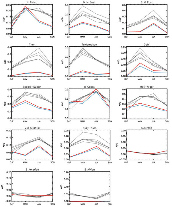
Offline dust emissions are now available for GEOS-Chem at native MERRA-2 (0.5° x 0.625°) and GEOS-FP (0.25° x 0.3125°) meteorology field resolution. This provides better quality dust emissions and emissions that are consistent regardless of model resolution. The offline emissions alter the seasonal distribution of dust emissions, especially the smaller source regions. We provide a brief comparison with AERONET coarse mode and regional estimates of seasonal dust AOD from satellite (Ridley et al., 2016) below. This will be included in the v11-03 release of GEOS-Chem; however, instructions to calculate the offline emissions and modify GEOS-Chem to use the offline emissions are included at the end of this document.
Motivation
Dust emissions scale non-linearly with wind speed and emission initiates from a limited number of locations. Both of these issues lead to a resolution-dependence of the dust emissions (e.g. Ridley et al., 2013). One way to alleviate this issue is to calculate the emissions offline using the native resolution GMAO meteorology and then read those emissions during run time. Unless the user intends on modifying the dust parameterization, we believe this is a suitable solution. Furthermore, the current method of applying a single global scaling factor to the dust emissions is a poor solution. Model resolution more strongly impacts dust emissions from weaker sources; therefore, the spatial and seasonal distribution of the emissions can change substantially as resolution is changed.
Methodology
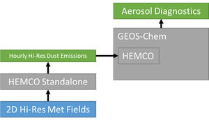
The modifications to switch to reading offline dust emissions are relatively simple. Firstly, we required the ‘reduced’ met fields, archived at Dalhousie from MERRA-2 and GEOS-FP reanalyses at native resolution. Using HEMCO standalone, we generate the dust emissions offline and output the hourly emissions for the four dust size bins. We altered the standard model HEMCO Configuration file to switch off the DEAD dust emissions module and to read dust emissions in from the HEMCO standalone diagnostic files instead. The offline emissions have no scale factor applied (e.g. 4.9x10⁻⁴ for MERRA-2 at 2.0° x 2.5°) so the user should apply the required scale factor in the HEMCO Configuration using the standard HEMCO scaling methodology (see the “implementation” section below). Moving the scale factor to the HEMCO Configuration, rather than in the model code, is more transparent and easier to alter. When running GEOS-Chem with the offline dust, HEMCO will interpolate the native resolution offline emissions to the current model resolution.
Testing
Firstly, we compare the emissions when calculating dust online at 2.0° x 2.5° and offline based on 2.0° x 2.5° offline emissions to ensure that the offline method produces similar results to online.
Globally, there are minor differences (<1%) between dust emissions calculated offline at 2.0° x 2.5° degree and dust emissions from the standard online GEOS-Chem methodology (Figure 2). The difference is most likely because the emission occurs hourly, rather than on the emission timestep. Also, small differences (<1%) exist in the temperature and pressure surface layer mid-point variables when read from the reduced meteorological variables by HEMCO in standalone mode, relative to via GEOS-Chem.
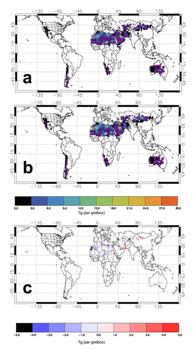
To test the impact of native resolution emissions on the dust we compare the offline 2.0° x 2.5° emissions with the 0.5° x 0.625° offline emissions from MERRA-2 in 2013. The native resolution emission are, on average, 40% greater than those calculated at 2.0° x 2.5° with the same scaling factor. However, even if the global emissions are scaled to match, there is spatial variation in the emissions (Figure 3). Generally, emissions in coastal and minor desert regions increase the most, relative to the 2.0° x 2.5° emissions. There is a relative decrease in African dust emissions when using the native resolution.
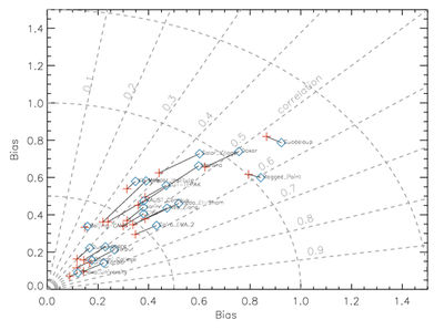
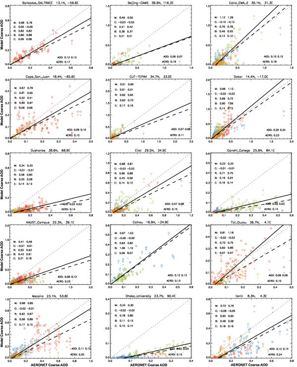
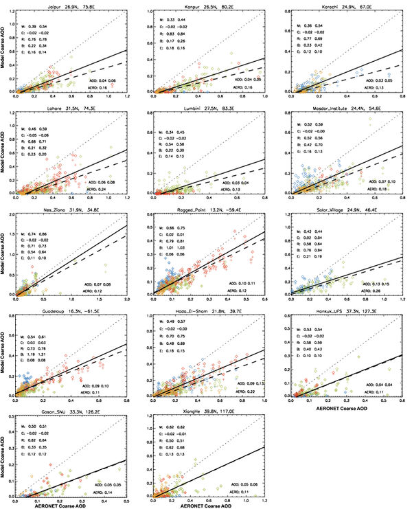
We use AERONET coarse AOD and satellite-derived dust AOD (Ridley et al., 2016) as the observational benchmark with which to compare the different emissions. This is not an evaluation of the dust scheme; the comparison simply indicates any relative changes in the agreement with observations and whether the proposed scaling factor for the offline emissions is reasonable. For comparison with AERONET coarse AOD we include the coarse sea-salt AOD from the model for completeness. However, the majority of sites are in locations with limited contribution from sea-salt aerosol. Comparison with daily AERONET coarse AOD indicates that there is a small increase in correlation and a reduction in bias when using the native resolution dust emissions (Figure 4). In most cases, the coarse AOD was previously underestimated in the model (at sites where AERONET coarse AOD is > 0.1 for 2013); therefore, the slope between model and observed coarse AOD is closer to the 1:1 line when comparing the two model versions with the same scaling factor (Figure 5). In some regions, such as sites in north-west Africa, the slope is often greater than the 1:1 line, primarily owing to too strong summertime dust emissions (red symbols on Figure 5).
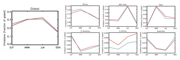
Figure 6 shows that the higher resolution emissions alter the seasonality of AOD in the key dust regions, but not dramatically. Globally, the 0.5° x 0.625° emissions redistribute the dust such that the summertime dust AOD increases more than the wintertime dust AOD decreases, yielding a slight improvement relative to the satellite-derived dust AOD estimates. The emissions from African regions decrease slightly relative to the other regions and decrease mostly in winter and spring. This change also brings the model into better agreement with the AOD estimated from the satellite observations. Interannual variability can be large over small regions; therefore, the satellite dust AOD estimates from 2004 – 2008 are only used as a guide when exploring the seasonality. However, regional and seasonal agreement between model and observations have a lot of room for improvement. Testing other emissions parameterizations and surface representation are an ongoing area of research.
Implementation of offline dust emissions in GEOS-Chem
You can find the HEMCO setup files for generation of the offline dust emissions, the diff patch (from v11-01), and the modified GEOS-Chem code to ingest the offline dust files can be found here:
MERRA-2: [1]
GEOS-FP: [2]
(contact mailto:daridley@mit.edu if these are not available)
The emissions are based on the reduced meteorological fields archived at Dalhousie from MERRA-2 and GEOS-FP at native resolution (0.5° x 0.625° and 0.25° x 0.3125°, respectively). By using offline dust, the GEOS-Chem model benefits from the higher spatial resolution of winds and soil moisture that control dust emissions. The dust emission scheme is identical to the standard implementation of the DEAD dust scheme in GEOS-Chem that relies on 2.0° x 2.5° source and soil texture maps, so is still limited in the same way in that regard. Future developments in the dust scheme provide an improved dust emission simulation can easily be converted into updated offline emissions files using this code (a year of MERRA-2 dust emissions are generated in a few hours).
HEMCO_sa_Config.rc sets the input/output folders and lists the variables required for dust emission. Ensure that these directories match your system. ".YYYMMDDhhmm.nc" will be appended to the end of the output DiagnPrefix The standalone code reads in met fields directly and maps them onto the variables required by the dust emissions code /HEMCO/Extensions/hcox_dustdead_mod.F. Those met fields are the reduced variable files "RED" that are processed and available from Dalhousie. You'll see them listed in the HEMCO_sa_Config as: /data/ctm/MERRA2_0.5x0.625/$YYYY/$MM/MERRA2.$YYYY$MM$DD.A1.05x0625.RED.nc4 /data/ctm/MERRA2_0.5x0.625/$YYYY/$MM/MERRA2.$YYYY$MM$DD.I3.05x0625.RED.nc4
Make sure the directory is correct and that both A1 and I3 files are available.
HEMCO_sa_Time.rc indicates the range of times for the emission calculation and the timestep. Emissions are calculated hourly as this is the output frequency, and the frequency at which the offline dust emissions are read into the GEOS-Chem model.
HEMCO_sa_Grid.rc specifies the HEMCO grid on which the emissions are calculated. This is set to the 0.5x0.625 MERRA-2 grid, but can be altered to the GEOS-FP grid size if reading in the reduced GEOS-FP met fields.
The species to be traced and the diagnostics to be output are included in HEMCO_sa_Spec.rc and HEMCO_sa_Diagn.rc
You will need to generate hemco_standalone.x by compiling GEOS-Chem with the following: make -j4 COMPILER=ifort MET=merra2 GRID=05x0625 CHEM=tropchem (or equivalent settings for GEOS-FP)
The GEOS-Chem model will unlikely compile at this resolution as a global model; however, it should get far enough to output the hemco_standalone.x into /bin/. If you are using an older version of the model there are minor changes to be made in CMN_SIZE_mod and Makefile_header that will allow compilation to proceed far enough with GRID=05x0625 or GRID=025x03125. These changes are included in the diff patch in the links (above) but below are quick explanations of the changes.
In Makefile_header.mk, comment out the error catching for when NEST is not set for the native resolutions (e.g. line 672 and 692):
   # Ensure that a nested-grid option is selected
   # Comment out so that HEMCO Standalone can be run globally at native resolution (DAR)
#    ifndef NEST
#      $(error $(ERR_NEST))
#    else
#      NEST_NEEDED    :=1
      USER_DEFS      += -DGRID05x0625
#    endif
Similarly, in /Headers/CMN_SIZE_mod.F, array sizes for native resolution without nested flags need setting, e.g. line 399:
# elif defined( GEOS_FP ) && defined( GRID025x03125 )
     !-----------------------------------------------------------------
     ! GEOS-FP Global
     !-----------------------------------------------------------------
     INTEGER               :: IGLOB      = 1152
     INTEGER               :: JGLOB      = 721
     INTEGER               :: LGLOB      = 72
#if   defined( GRIDREDUCED )
     INTEGER               :: LLPAR      = 47        ! Reduced vertical grid
     INTEGER,    PARAMETER :: LLTROP_FIX = 38        !  -- 47 levels
     INTEGER,    PARAMETER :: LLTROP     = 38
     INTEGER,    PARAMETER :: LLSTRAT    = 44
#else
     INTEGER               :: LLPAR                  ! Full vertical grid
     INTEGER,    PARAMETER :: LLTROP_FIX = 40        !  -- 72 levels
     INTEGER,    PARAMETER :: LLTROP     = 40
     INTEGER,    PARAMETER :: LLSTRAT    = 59
#endif
---
Once everything is set up, run hemco_standalone.x and the dust emissions will be output in the selected directory.
N.B. Dust emissions will be saved with no scaling factor. This is applied to the tracers when they are read in via HEMCO_Config.rc
N.B. The reduced meteorological files sometimes cause the HEMCO standalone run to crash. The cause is not clear, but an addition to hco_geotools_mod.F fixes most of these (available in the diff patch for GEOS-FP, linked above).
The GEOS-Chem model can now be run using offline dust emissions by:
Switching off DustDead (105) and DustGinoux (106) extensions in HEMCO_Config.rc will activate the offline dust. The location of the emissions to read in are required and should be added in “SECTION BASE EMISSIONS” as follows:
#==========================================================================
# --- OFFLINE DUST ---
#==========================================================================
# 0.5 x 0.625
0 EMIS_DST1 /net/seurat/data/ctm/offline_dust_0625/$YYYY/dust_emissions_0625.$YYYY$MM$DD$HH00.nc EMIS_DST1 1980-2017/1-12/1-31/0-23 C xy kg/m2/s DST1
606 1 2
0 EMIS_DST2 /net/seurat/data/ctm/offline_dust_0625/$YYYY/dust_emissions_0625.$YYYY$MM$DD$HH00.nc EMIS_DST2 1980-2017/1-12/1-31/0-23 C xy kg/m2/s DST2
606 1 2
0 EMIS_DST3 /net/seurat/data/ctm/offline_dust_0625/$YYYY/dust_emissions_0625.$YYYY$MM$DD$HH00.nc EMIS_DST3 1980-2017/1-12/1-31/0-23 C xy kg/m2/s DST3
606 1 2
0 EMIS_DST4 /net/seurat/data/ctm/offline_dust_0625/$YYYY/dust_emissions_0625.$YYYY$MM$DD$HH00.nc EMIS_DST4 1980-2017/1-12/1-31/0-23 C xy kg/m2/s DST4
606 1 2
This will point to the offline hourly dust emissions and extract the EMIS_DSTX variables and to be put into the DSTX tracers in place of the online calculation.
Because the offline emissions are saved without a scale factor, a scaling factor for dust must be included near the end of the HEMCO_Config.rc file in the SECTION SCALE FACTORS:
606 DUST_EMISSIONS 0.0005 - - - xy 1 1
The offline dust read statements above use the 606 line to apply the scale factor to the emissions. We advise a scaling factor of 0.0005 for 0.5° x 0.625° emissions and 0.0004 for 0.25° x 0.3125° emissions, based on a comparison with AERONET for 2013. However, the scale factor may need adjusting slightly for other years or if focusing on particular regions.
--David Ridley (talk) 20:09, 29 April 2018 (UTC)
Computing PM2.5 concentrations from GEOS-Chem output
For information on how to compute particulate matter (PM2.5) from GEOS-Chem diagnostic outputs, please see our Particulate matter in GEOS-Chem wiki page.
--Bob Yantosca (talk) 21:13, 10 February 2016 (UTC)
Previous issues that are now resolved
The following bugs and/or technical issues with the GEOS-Chem mineral dust simulation have now been resolved.
Bug in ND21 diagnostic indexing for size-resolved dust species
This fix was included in v11-02a and approved on 12 May 2017.
Chris Holmes wrote:
I’ve found a bug in the ND21 aerosol diagnostics in v11-01. [I tried to plot...] the surface area density of sea-salt aerosols (tracers 14017, 14020). The data in the bpch file must be some dust property, however, since it is concentrated over Africa, not the ocean. I’ve found this problem in v11-01 4x5 GEOS5 using both SOA chemistry and UCX chemistry.
Bob Yantosca replied:
Basically the counter for ND21 in GeosCore/dust_mod.F was off by 5 slots. To fix this, we have removed the code in RED was removed, and added the code in GREEN.
                 ! There are always 5 + (NRHAER*23) preceding size-res dust
                 ! Each subsequent set is separated by a further distance of
                 ! (NRHAER + NDUST)
     !-----------------------------------------------------------------------------
     ! Prior to 3/27/17:
     ! This formula for NOUT caused the size-resolved dust AOD's to be written
     ! to slots 16-22 of AD21, thus overwriting other diagnostics.  They should
     ! be written to slots 21-27.  Change the NRHAER*2 to NRHAER*3 to make the
     ! counting come out right.  This is just an empirical fix.  Maybe the issue
     ! was caused by a modification in aerosol_mod.F. (cdh, bmy, 3/27/17)
     !            NOUT = 5 + (NRHAER*2) + ((NRHAER+NDUST)*(W-1)) + N
     !-----------------------------------------------------------------------------
                 NOUT = 5 + (NRHAER*3) + ((NRHAER+NDUST)*(W-1)) + N
--Bob Yantosca (talk) 19:35, 27 March 2017 (UTC)
Bug fixes for hydrophobic aerosol properties
This update was validated with 1-month benchmark simulation v11-01f and 1-year benchmark simulation v11-01f-geosfp-Run0. This version was approved on 16 Apr 2016.
Seb Eastham identified several bugs setting hydrophobic aerosol properties in aerosol_mod.F, as described below.
Hydrophobic aerosol properties fix (1 of 2):
   The order of operations in calculating the "average" radius for
   mixed hydrophilic and hydrophobic aerosol was resulting in the
   following calculation:

   r = ((r_dry * A_dry) + (r_wet * (A_dry + A_wet)))/(A_dry + A_dry + A_wet)

   This has now been changed to:

   r = ((r_dry * A_dry) + (r_wet * A_wet))/(A_dry + A_wet)

   This will slightly decrease the mean radius of BC and OC. This is the
   first of two connected corrections.

   Old code:
                 TAREA(JLOOP,N+NDUST) = TAREA(JLOOP,N+NDUST) + DRYAREA
                 ERADIUS(JLOOP,NDUST+N) = ( ERADIUS(JLOOP,NDUST+N) *
    &                                       TAREA(JLOOP,N+NDUST)   +
    &                                       RW(1) * DRYAREA )      /
    &                                     ( TAREA(JLOOP,N+NDUST)   +

   New code:
                 TAREA(JLOOP,N+NDUST) = WTAREA(JLOOP,N+NDUST) + DRYAREA
                 ERADIUS(JLOOP,NDUST+N) = ( WERADIUS(JLOOP,NDUST+N) *
    &                                       WTAREA(JLOOP,N+NDUST)   +
    &                                       RW(1) * DRYAREA )      /
    &                                     ( WTAREA(JLOOP,N+NDUST)   +
Hydrophobic aerosol properties (fix 2 of 2):
   When calculating total SAD and radius of BC and OC, the properties
   of the hydrophobic component were calculated using a radius which
   was given in um but expected to be in cm. As a result, the additional
   SAD due to hydrophobic aerosol was underestimated by x10,000, and the
   average aerosol radius was overestimated in a similar fashion. This
   has been corrected by applying a 1.0D-4 factor wherever RW(1) is
   referenced. This is the second of two connected corrections.

   Old code:
                  DRYAREA = 3.D0 * DAERSL(I,J,L,N-1) / ( RW(1) *
     &                      MSDENS(N) )
                  ERADIUS(JLOOP,NDUST+N) = ( WERADIUS(JLOOP,NDUST+N) *
     &                                       WTAREA(JLOOP,N+NDUST)   +
     &                                       RW(1) * DRYAREA )      /
     &                                     ( WTAREA(JLOOP,N+NDUST)   +
     &                                       DRYAREA )

   New code:
                  DRYAREA = 3.D0 * DAERSL(I,J,L,N-1) / ( RW(1) *
     &                      1.0D-4 * MSDENS(N)
                  ERADIUS(JLOOP,NDUST+N) = ( WERADIUS(JLOOP,NDUST+N) *
     &                                       WTAREA(JLOOP,N+NDUST)   +    /
     &                                       RW(1) * 1.0D-4 * DRYAREA )/
     &                                     ( WTAREA(JLOOP,N+NDUST)   +
     &                                       DRYAREA )
Fixed indexing bug for WTAREA in aerosol_mod:
   WTAREA was incorrectly indexed in aerosol mod, resulting in
   zero SAD for non-dust aerosols and overwriting of dust SAD
   by other aerosol data. This only affects carbonaceous aerosol
   calculations in carbon_mod.

   Old code:
              WTAREA(JLOOP, N)   = TAREA(JLOOP, N+NDUST)
              WERADIUS(JLOOP, N) = ERADIUS(JLOOP, N+NDUST)

   New code:
              WTAREA(JLOOP, N+NDUST)   = TAREA(JLOOP, N+NDUST)
              WERADIUS(JLOOP, N+NDUST) = ERADIUS(JLOOP, N+NDUST)
--Lizzie Lundgren (talk) 19:16, 5 January 2016 (UTC)
--Bob Yantosca (talk) 15:24, 30 March 2016 (UTC)
Bug fix for offline dust aerosols when UCX is on
This update was validated with 1-month benchmark simulation v11-01d and 1-year benchmark simulation v11-01d-Run1. This version was approved on 12 Dec 2015.
Seb Eastham wrote:
- On or around line 1450 of dust_mod.F [in v10-01], the dry radius and extinction of dust are retrieved from QQAA and RDAA. If RRTMG is active, the single scattering albedo and asymmetry factors are also retrieved, from SSAA and ASYMAA. However, they are always read from entry [X,Y,Z,6] of the corresponding array.
- Unfortunately, this index is only correct if the UCX is off; if the UCX is on, the entry should be 8, not 6 (based on fast_jx_mod, where these arrays are populated). It looks like an index variable was prepared for this purpose but it's not used. As it is, when the UCX is on, dust radius, surface area and scattering will actually be calculated based on stratospheric sulfate aerosol properties.
--Lizzie Lundgren (talk) 15:51, 23 October 2015 (UTC)
Now treat DST2-DST4 as coarse mode in wet scavenging
This fix was validated with 1-month benchmark simulation v11-01b and 1-year benchmark simulation v11-01b-Run0. This version was approved on 19 Aug 2015.
While resolving some of the conflicts in the acid uptake on dust aerosol code (based on v8-01-01), it was brought to Duncan Fairlie's attention that we now use different scavenging coefficients for fine and coarse aerosols. In GEOS-Chem v9-01-03, we implemented Qiaoqiao Wang's updates for aerosol scavenging efficiency. With this update, we now calculate WASHFRAC for accumulation mode and coarse mode aerosol using washout efficiency from Feng (2007). This paper has efficiency for aerosol sizes 0.001-0.04 μm, 0.04-2.5 μm (accumulation mode), 2.5-16 μm (coarse mode) and 16-100 μm. Based on those numbers, Qiaoqiao used accumulation mode for DST1-DST3 and coarse mode for DST4. Duncan has suggested that we revisit what we consider fine and coarse mode for dust in the wet deposition code. He suggests we treat DST1 as accumulation mode and DST2-DST4 as coarse mode.
The dust size bins are currently defined as:
- DST1: 0.1–1.0 μm
- DST2: 1.0–1.8 μm
- DST3: 1.8–3.0 μm
- DST4: 3.0–6.0 μm
Jeff Pierce wrote:
- The dust bin sizes you provide are radius, whereas the efficiencies diameter (weird that accumulation mode could go up to D=5 μm... even 2.5 μm is big for accumulation mode). Thus, we need to multiply the dust-bin sizes by 2. In which case DST3 and DST4 are both coarse and DST2 sits in between (with a larger fraction in coarse). I support Duncan's suggestion.
- We should stop the use of radius for aerosol size measurements. It's a minority, and causes errors and confusion in cases such as this.
--Melissa Sulprizio (talk) 19:01, 20 July 2015 (UTC)
Known issues
The following issues have not yet been resolved. These are active problems of research.
Low bias at 4x5 resolution
The following comments are in the documentation header to source code file dust_dead_mod.f, which is the implementation of Zender's DEAD scheme in GEOS-Chem:
T. Duncan Fairlie wrote:
- NOTE: The current [dust] code was validated at 2 x 2.5 resolution. We have found that running at 4x5 we get much lower (~50%) dust emissions than at 2x2.5. Recommend we either find a way to scale the U* computed in the dust module, or run a 1x1 and store the the dust emissions, with which to drive lower resolution runs.
- -- Duncan Fairlie, 1/25/07
Daniel Jacob wrote:
- NOTE: [We'll] implement the [dust] code in the standard [GEOS-Chem] model and put a warning about expected low bias when the simulation is run at 4x5. Whoever is interested in running dust at 4x5 in the future can deal with making the fix.
- -- Daniel Jacob, 1/25/07
--Bob Y. 10:34, 22 February 2010 (EST)
References
- Chin, M., P. Ginoux, S. Kinne, B. Holben, B. Duncan, R. Martin, J. Logan, A. Higurashi, and T. Nakajima, Tropospheric aerosol optical thickness from the GOCART model and comparisons with satellite and sunphotometers measurements, J. Atmos Sci., 2001.
- Chin, M., et al., Aerosol distribution in the Northern Hemisphere during ACE-Asia: results from global model, satellite observations, and Sun photometer measurements, J. Geophys. Res., 109, D23S90, 2004.
- Fairlie, T.D., D.J. Jacob, J.E. Dibb, B. Alexander, M.A. Avery, A. van Donkelaar, and L. Zhang, Impact of mineral dust on nitrate, sulfate, and ozone in transpacific Asian pollution plumes, Atmos. Chem. Phys., submitted, 2010. PDF
- Fairlie, T. D., D.J. Jacob, and R.J. Park, The impact of transpacific transport of mineral dust in the United States, Atmos. Environ., 41, 1251-1266, 2007. PDF
- Gillette, D.A., Passi, R., Modeling dust emission caused by wind erosion, J. Geophys. Res., 93, 14,233–14,242, 1988.
- Ginoux, P., et al., Sources and distributions of dust aerosols simulated with the GOCART model, J. Geophys. Res, 106 (D17), 20255–20274, 2001.
- Ginoux, P., et al., Long-term simulation of global dust distribution with the GOCART model: correlation with North Atlantic oscillation, Environmental Modeling and Software, 19, 113–128, 2004.
- Ridley, D. A., C. L. Heald, and B. J. Ford, North African dust export and deposition: A satellite and model perspective, J. Geophys. Res., doi:10.1029/2011JD016794, in press, 2011.
- White, B.R., Soil transport by winds on Mars, J. Geophys. Res., 84, 4643–4651, 1979.
- Zender, C.S., Bian, H., Newman, D., The mineral dust entrainment and deposition (DEAD) model: description and 1990s dust climatology, J. Geophys. Res, 108 (D14), 4416, 2003a.
- Zender, C.S., Newman, D., Torres, O., Spatial heterogeneity in aeolian erodibility: uniform, topographic, geomorphic and hydrologic erodibility, J. Geophys. Res., 108 (D17), 4543, 2003b.
- Zhang, L., Gong, S., Padro, J., Barrie, L., A size-segregated particle dry deposition scheme for an atmospheric aerosol module, Atm. Environ., 35, 549–560, 2001.
--Melissa Payer 14:35, 3 January 2012 (EST)
